Lithium-ion News

How to Choose the Best Custom Battery Pack Manufacturer for Your Industry
Choosing a custom battery pack manufacturer impacts production times and shapes how your systems perform under pressure. As more businesses require battery solutions that meet specific technical requirements, the need...
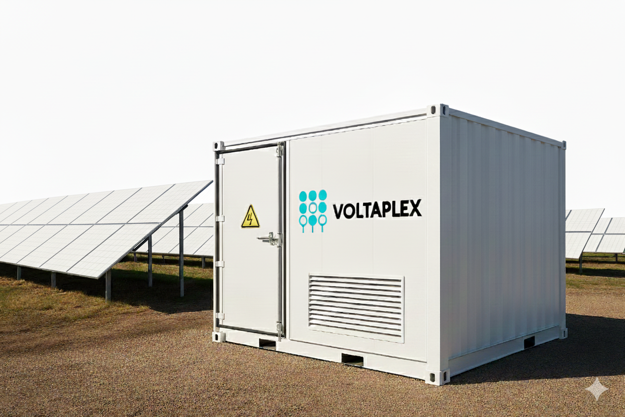
Voltaplex Launches Complete Battery Energy Storage Systems (BESS)
Voltaplex now offers complete Battery Energy Storage Systems (BESS), combining trusted LFP and NMC cell technology—including our long-life Voltaplex Life™ cells—with fully integrated, scalable solutions and a 10-year standard warranty.

Lead-Acid Replacement Batteries: Why Lithium Is the Smarter Choice
Looking to upgrade from bulky, short-lived lead-acid batteries? Discover why lithium is the smarter choice. This article explores the advantages of LiFePO4 technology and introduces Voltaplex's standard 12V battery packs—VPMB-12200...

Hassle-Free Shipping of Lithium-Ion Batteries with Voltaplex
Hassle-Free Shipping of Lithium-Ion Batteries with Voltaplex Shipping lithium-ion (Li-ion) batteries is a complex process due to stringent safety regulations, classification requirements, and carrier restrictions. Given the potential risks associated...

Understanding Certifications for Custom Battery Packs
Understanding Certifications for Custom Battery Packs Custom battery packs are designed to meet specific application requirements, making them highly specialized solutions. At Voltaplex, we develop custom battery packs with unique...

Ensuring quality through rigorous battery testing at Voltaplex
At Voltaplex, we take pride in delivering batteries that meet the highest standards of safety, performance, and reliability. Every battery produced undergoes a meticulous testing process to ensure it functions...

Understanding lithium iron phosphate (LFP) batteries and their applications
Lithium Iron Phosphate (LFP) batteries are gaining popularity in various industries due to their unique advantages over other types of lithium-ion batteries. In this article, we will explore what makes...
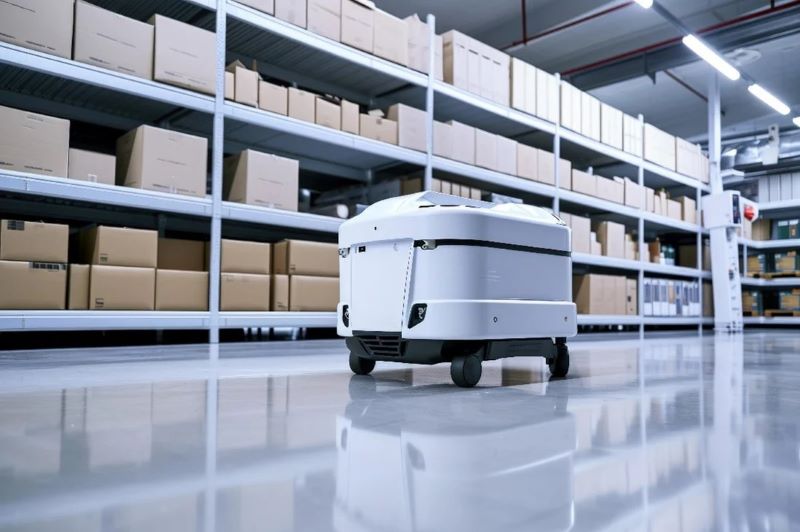
The role of automated grid vehicles (AGVs) in revolutionizing the warehouse industry
The warehouse industry is undergoing a significant transformation, driven by the increasing demand for efficiency, accuracy, and speed. One of the key technologies at the forefront of this revolution is...
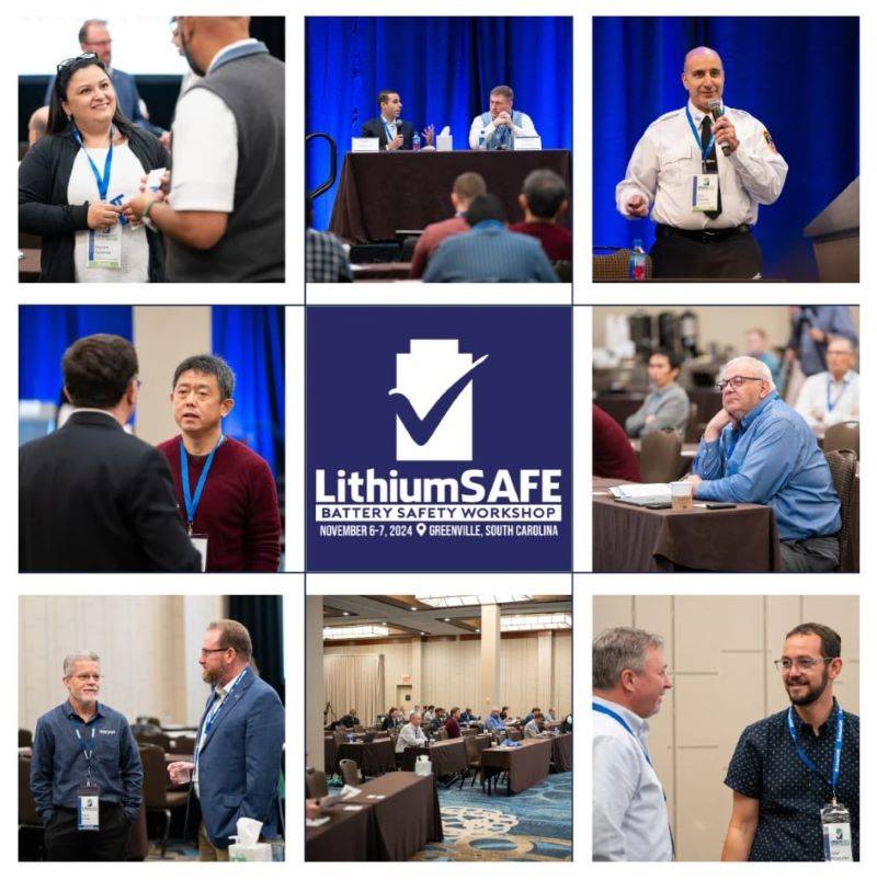
Rare but ferocious
As part of our LithiumSAFE Conference, we held a panel on how to speak about battery safety in the marketplace. Panelists included Jim Greenberger, Executive Director of NAATBatt, Brian Engle,...

Let's save the heros
Last Sunday at an Aricell plant in South Korea, the workers heard some popping noises, and saw smoke coming from a large stack of loose lithium metal primary cells, packaged...